Our Services

At APC, we deliver fully integrated solutions in construction, architectural design, engineering, and project management, providing each client with a service tailored to the specific requirements of their property and objectives.
We specialize in residential development, offering complete support from concept and feasibility studies to permitting, drafting, and final construction execution. Every project is designed to meet the highest standards of quality, safety, sustainability, and cost efficiency.
Our multidisciplinary technical team brings extensive experience in plan preparation, permit acquisition, zoning compliance, and field implementation, allowing us to streamline approval timelines and minimize delays.
Whether building on flat terrain, hillside lots, or challenging urban lots, we provide strategic planning and precise documentation to ensure long-lasting, functional, and code-compliant results. From small remodels to full-scale developments, we approach every project with engineering precision and client-focused coordination.

Core Engineering Services (APC)
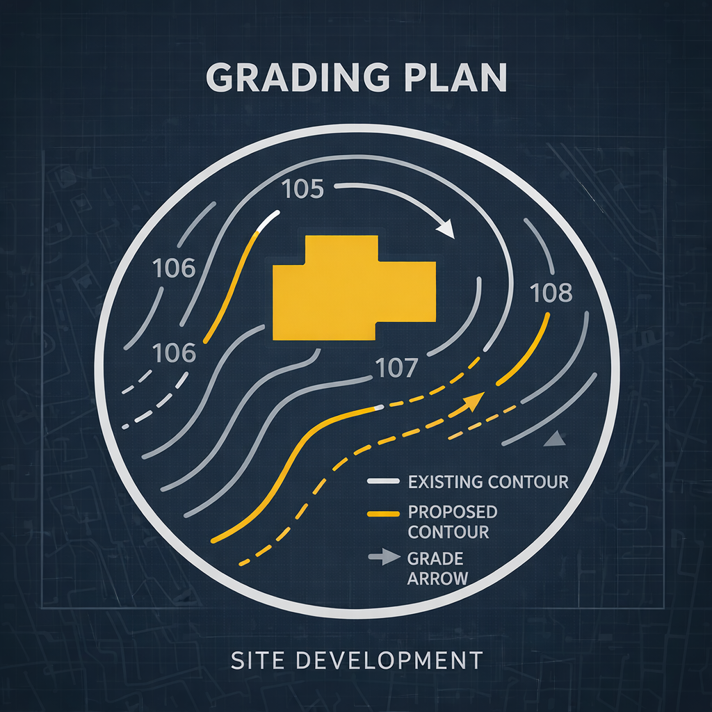
Grading Plans
A plan showing how the land will be graded and shaped for a project. It indicates the elevations, slopes, cuts, and fills necessary to ensure proper drainage and prepare the site for construction. It is essential to prevent flooding.
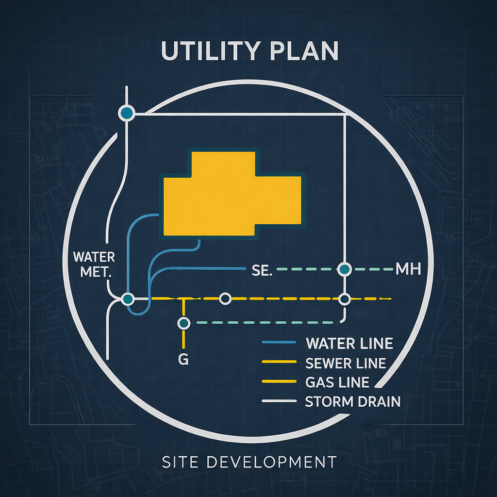
Utility Plans
It is a plan that shows the location and layout of underground and overhead utility installations, such as water, sewer, electricity, gas, and telecommunications. It helps coordinate the safe installation of these networks and avoids conflicts during construction.
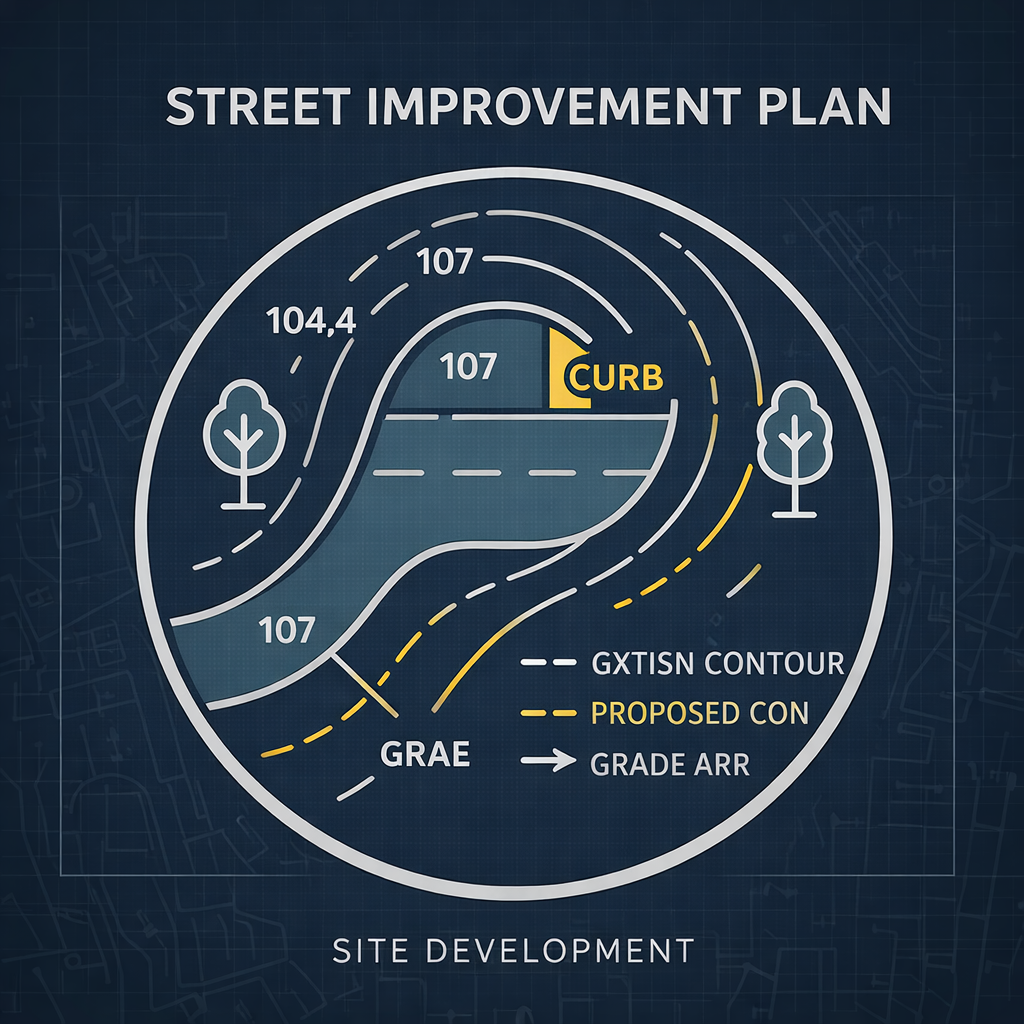
Street Improvement Plans
This plan details proposed improvements to streets and roadways, such as paving, sidewalks, curbs, ramps, signage, and drainage. Its purpose is to improve safety, accessibility, and functionality for vehicular and pedestrian traffic, while meeting municipal standards.
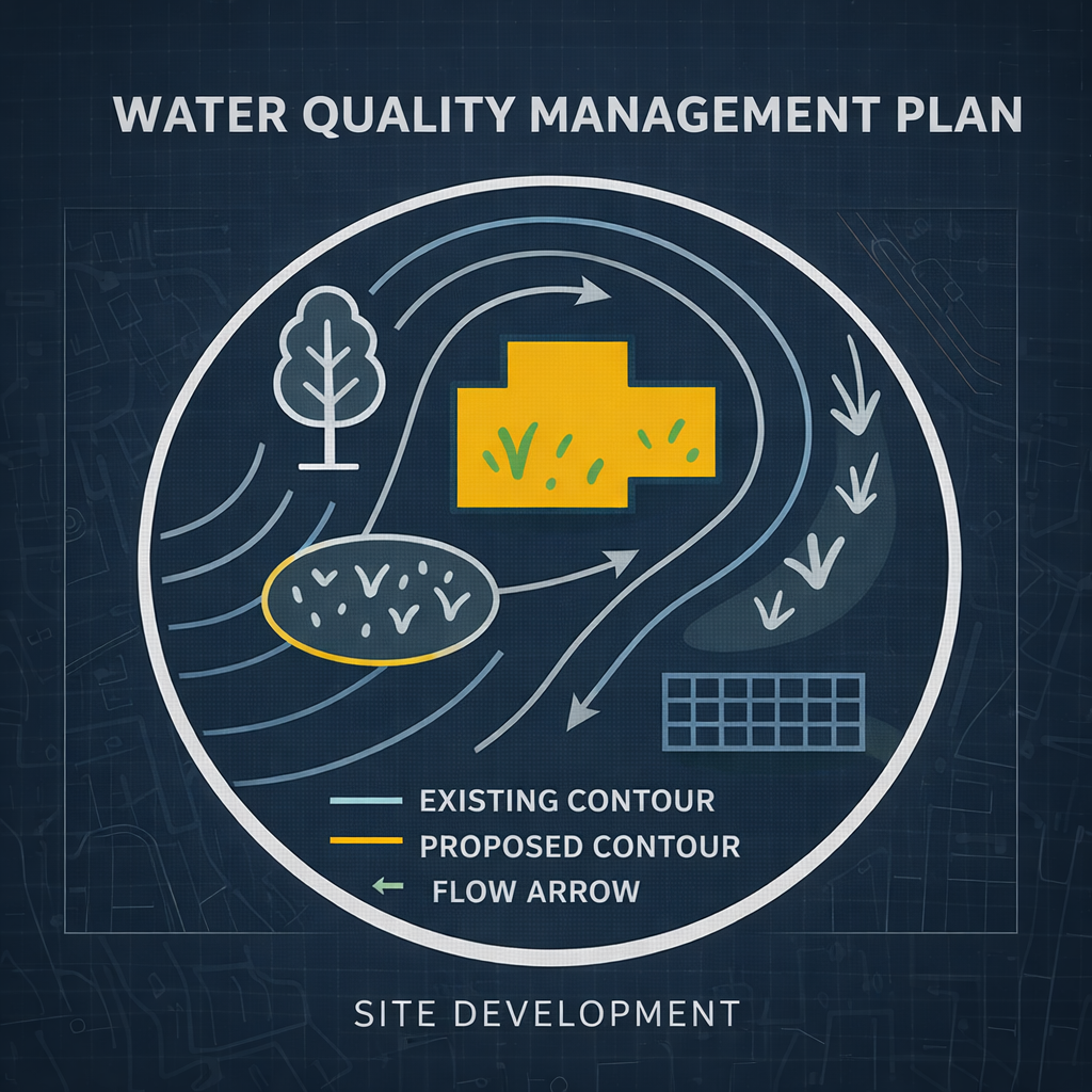
Water Quality Management Plan
(WQMP) is a technical document that describes the strategies and measures to be implemented in a project to minimize stormwater pollution. Its objective is to protect water quality by controlling runoff, filtering pollutants, and complying with local and state environmental regulations.
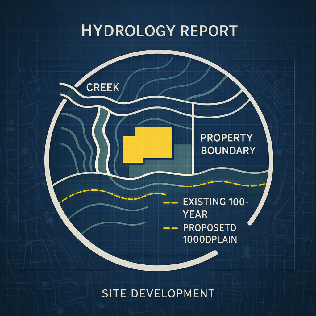
Hydrology Reports
It is a technical study that analyzes how rainwater flows through a site. It includes calculations of runoff, flood zones, and drainage capacity. Its purpose is to ensure that the project design adequately manages stormwater, preventing flooding and meeting the authorities' hydraulic requirements.
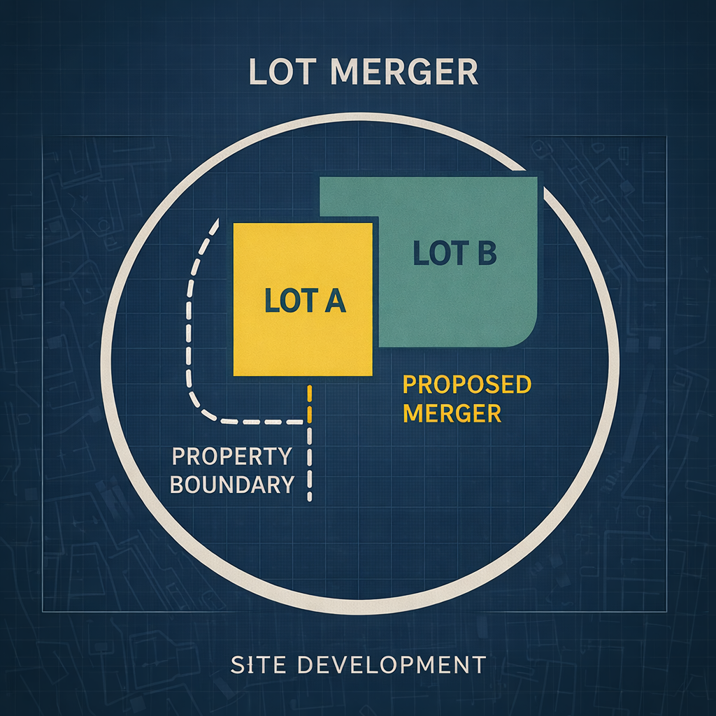
Lot Merger
It is the legal and technical process by which two or more contiguous lots are combined into a single property. This procedure is used to facilitate larger developments, comply with zoning requirements, or simplify ownership. It requires approval from the local authority and is usually accompanied by plans and official documentation.

Corner Records
It is a technical document used to officially record, reestablish, or mark the location of corners or monuments of property lines, sections, or subdivisions. It is typically prepared by a licensed surveyor and filed with the county to ensure the accuracy and permanence of the legal boundaries of the land.

Report of Survey
It is an official document prepared by a licensed surveyor that shows the results of a land survey. It includes information about property boundaries, monuments found or placed, legal discrepancies, and other relevant details.

Construction Staking
It is the process of marking the exact locations of construction elements, such as foundations, curbs, pipes, or structures, on the site based on project plans. These marks guide contractors throughout the project to ensure everything is built accurately and according to the approved design.

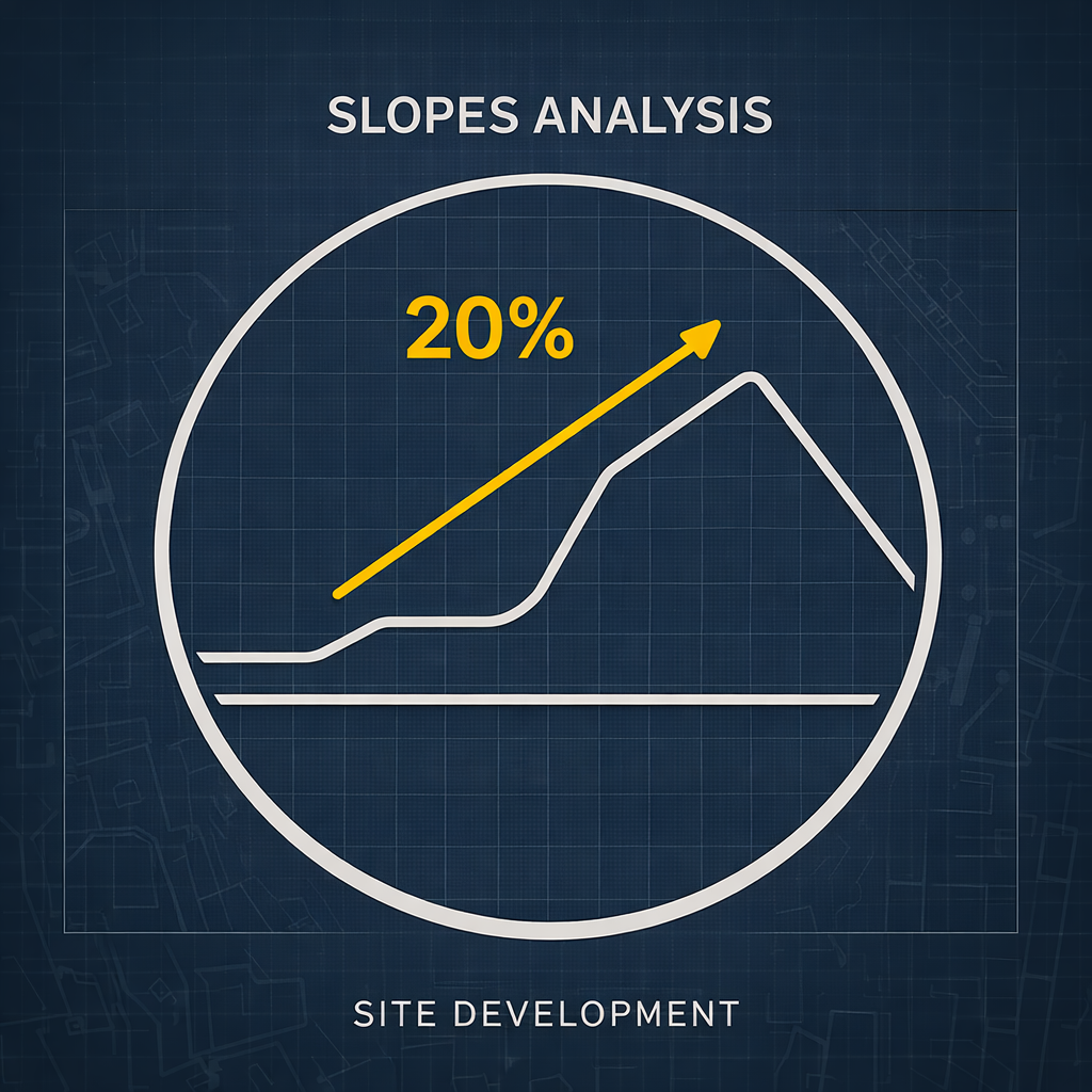
Slope Analysis
It is a study that evaluates land slopes to identify areas at risk of landslides, erosion, or drainage problems. It is essential in construction and urban development projects, as it helps determine soil stability, the appropriate design of slopes, and the viability of development based on the natural topography.
Architectural Services
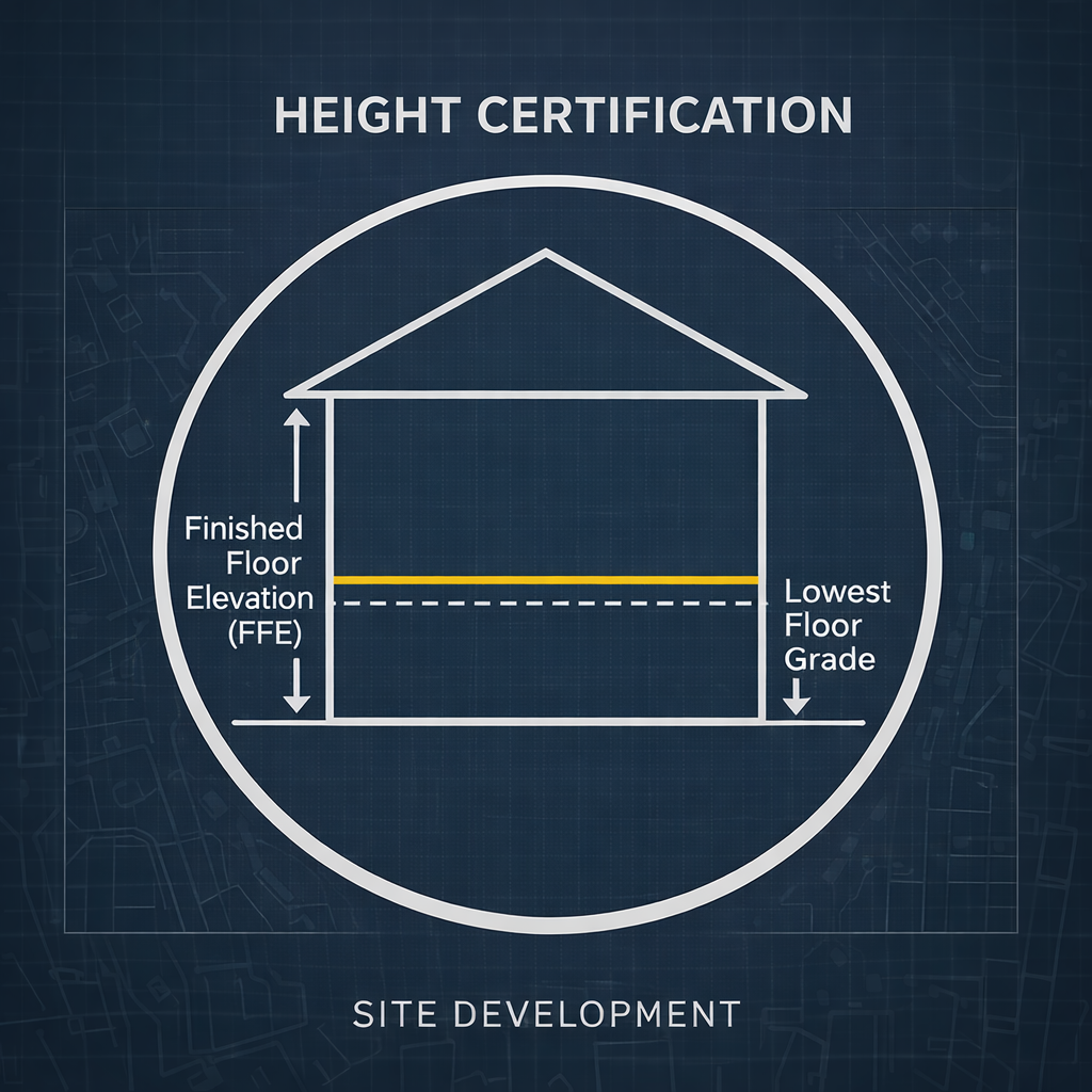
Height Certification
A certified surveyor's certificate is a document issued by a licensed surveyor that verifies the height of a constructed structure relative to a specific reference point, such as sea level or natural terrain. This certificate ensures that the building complies with the height limits established by local zoning or aviation regulations.

Topographic Survey Map
It is a detailed plan that shows the physical and natural features of a site, including elevations, slopes, trees, buildings, bodies of water, and other visible structures. This type of survey is essential for the design and planning of construction projects, as it provides an accurate representation of the site's surface.
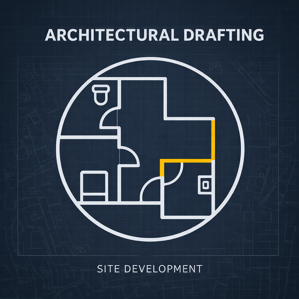
Architectural Drafting
Our precise architectural drafting services include floor plans, elevations, and sectional views. Our team supports all project phases from conceptual design to final documentation, ensuring clarity, compliance, and constructability.
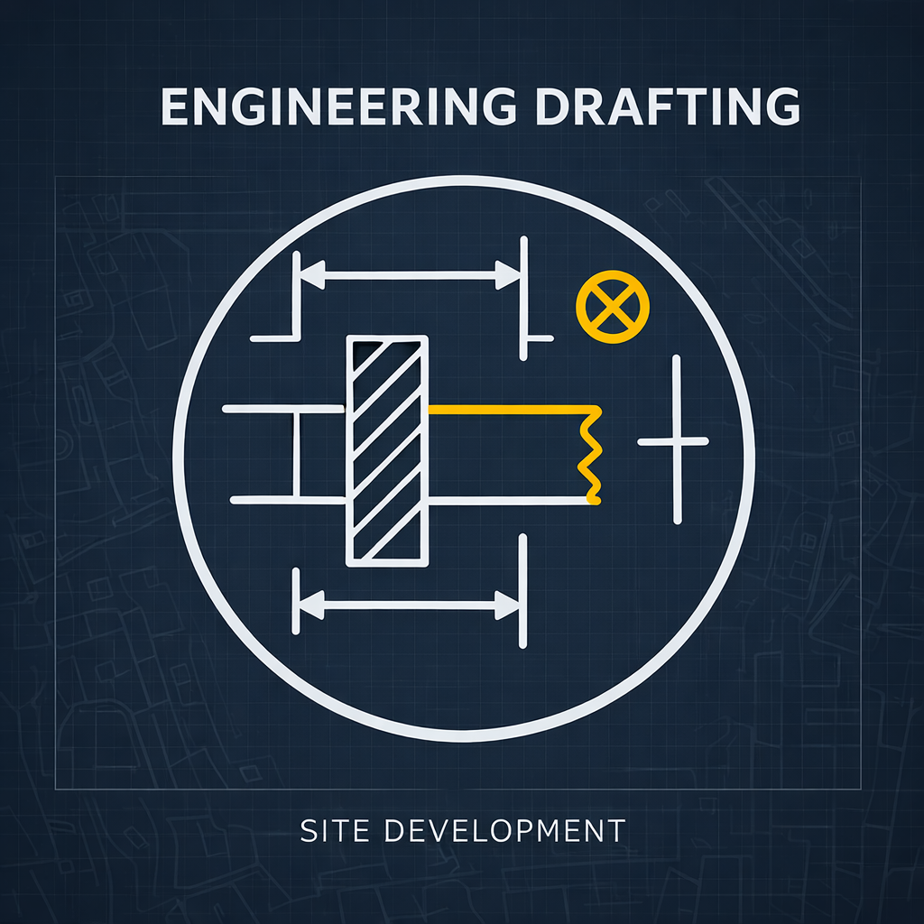
Engineering Drafting
We deliver detailed drafting services for structural, electrical, mechanical, and plumbing (MEP) systems. Our documents ensure clear coordination across disciplines, helping engineers and contractors execute projects with accuracy and confidence.

2D CAD and 3D modeling
Using the latest software, we develop detailed 2D CAD drawings and 3D models to bring your designs to life. Our 2D drawings ensure clarity and documentation precision, while our 3D models help with visualization, coordination, and early-stage design validation.

Detailed technical documentation
We provide thorough technical documents that support smooth project approvals and reliable construction execution. From annotations and notes to material specifications and compliance checklists, every document is carefully reviewed for accuracy.
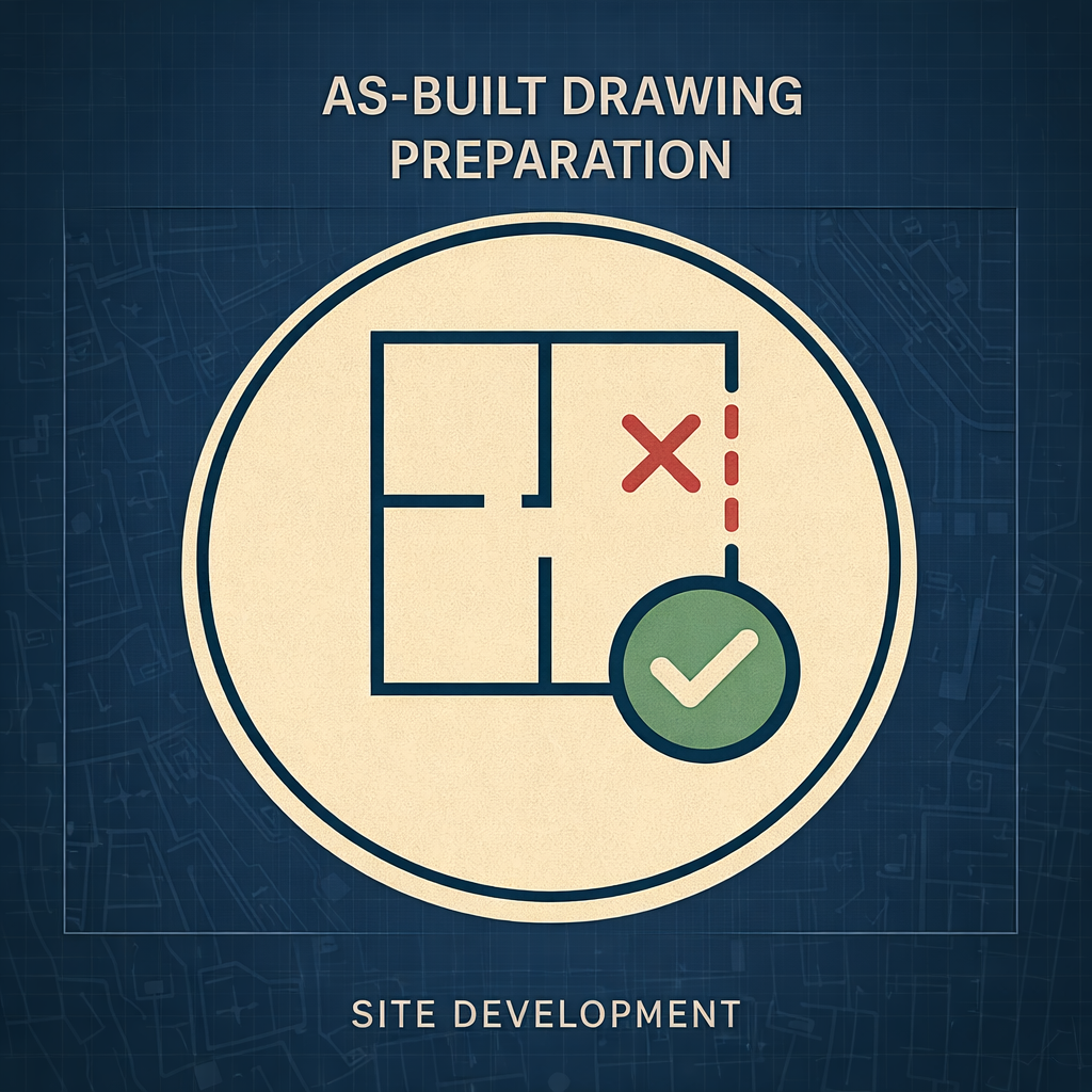
As-Built Drawing Preparation
Post-construction, we generate as-built drawings that accurately reflect all final installations, dimensions, and design changes made during execution. These documents serve as essential records for future renovations, maintenance planning, and legal documentation.

Building Information Modeling (BIM)
We create data-rich 3D BIM models that support advanced planning, real-time collaboration, and lifecycle management. These models allow early clash detection, reduce change orders, and improve accuracy across architectural and engineering teams.

CAD conversion and redrafting
Whether you have hand-drawn sketches, PDFs, or scanned blueprints, we can convert them into clean, editable CAD files. Our redrafting process ensures layer consistency, scale accuracy, and integration readiness for future design phases. This is ideal for renovation projects, or regulatory compliance.

Clash detection and coordination
We identify design conflicts early by running clash detection across disciplines within BIM models. This helps resolve coordination issues before they reach the construction site, reducing costly delays and rework. Our team documents all clashes with suggested resolutions, ensuring collaboration.

Sewer Plan
A technical drawing that illustrates the routing, slope, and connection points of underground sewer lines. It ensures proper wastewater flow, compliance with municipal standards, and seamless coordination with other utility systems.

Retaining Wall Plans
Detailed structural drawings that define the dimensions, materials, footing design, and drainage configuration of retaining walls. They guarantee slope stabilization and long-term durability under lateral earth pressure.
Slopes Analysis
A topographical assessment that identifies terrain gradients and elevation changes to determine buildability, drainage direction, and grading requirements before construction.
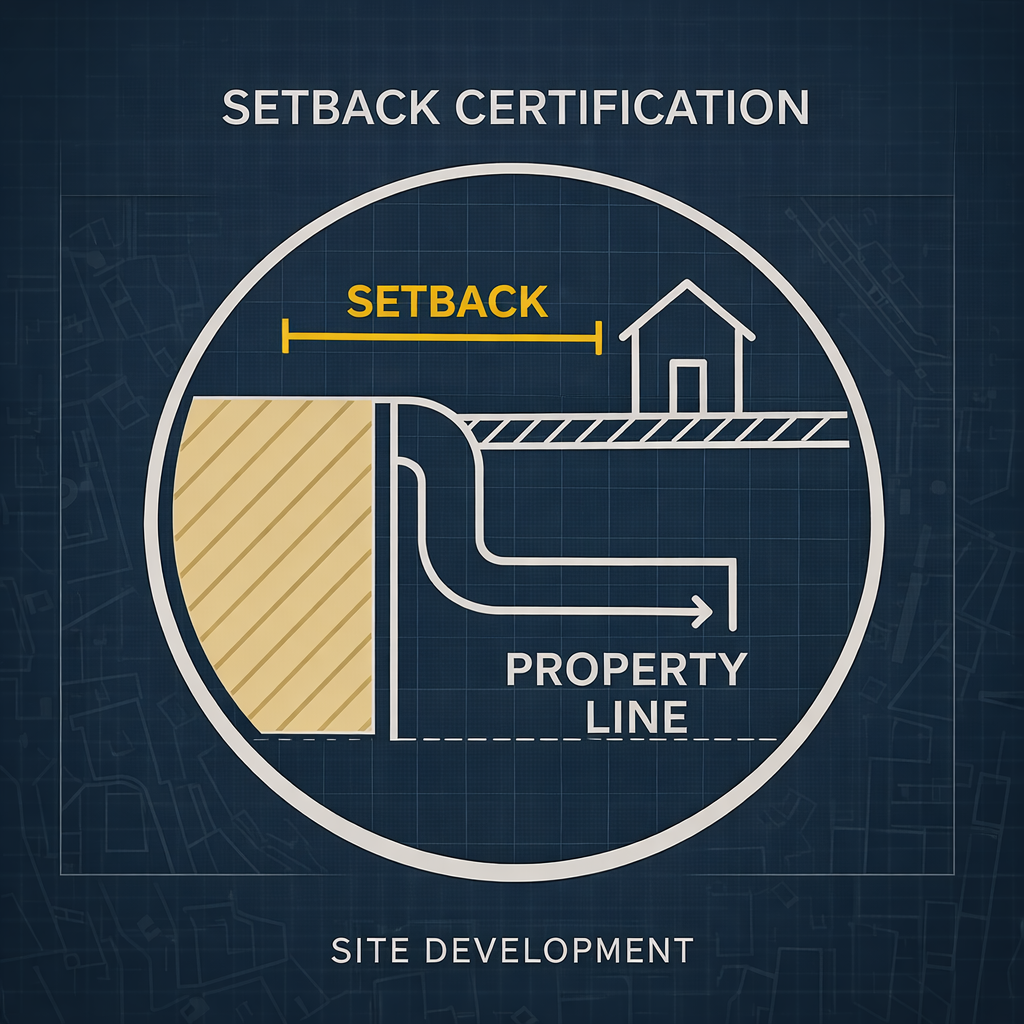
Setback Certification
A verified document that demonstrates the required distance between a structure and property boundaries. It confirms compliance with zoning regulations before permitting or inspection.

Construction Staking
A field layout process where surveyors mark the exact locations of proposed structures, utilities, and grading features on-site. It guides contractors during construction to ensure accurate placement according to approved plans.

Boundary Survey
A precise measurement of property lines and corner markers to establish legal ownership limits. It is required for land transactions, fencing, development, and resolving any encroachment or title disputes.

Elevation Certificate
A FEMA-compliant document that provides accurate elevation data of a structure relative to floodplain levels. It is used for flood insurance rating, permitting, and assessing potential flood risk.

Plan of Survey
A formal drawing that consolidates boundary measurements, easements, improvements, and site features into a single document. It serves as a legal reference for land use planning, permitting, and property development.